Acquisition Electronics
PMTs and amplifiers
We use a variety of PMTs from Hamamatsu. Our workhorse PMTs are the H7420 series, which are head-on PMTs
with 5 mm and 3 mm diameter active areas respectively, as well as some conventional photocathode PMTs, but with newer improved photocathodes.
The UBA series have large 30x30 mm active areas, making them good for external detectors on two-photon systems. They are also more
resistant to high light damage compared to GaAsP PMTs (which have a built-in high limit protection and turn off ).
 The preamplifiers we use have two outputs, a DC-coupled output that is fed into the amplifier on the digitizer board where it is further
amplified and a black level adjustment added, and a second AC-coupled output for photon counting and TCSPC.
The preamplifiers we use have two outputs, a DC-coupled output that is fed into the amplifier on the digitizer board where it is further
amplified and a black level adjustment added, and a second AC-coupled output for photon counting and TCSPC.
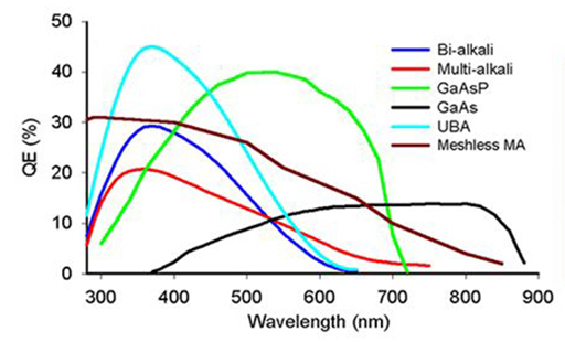
- H7420-40: GaAsP (Gallium Arsenide Phosphide) photocathode PMT for high sensitivity in the UV to ~720 nm.
- H7420-50: GaAs (Gallium Arsenide) photocathode PMT with a lower quantum efficiency but with NIR sensitivity out to 890 nm.
- R7600-200 Hamamatsu Ultra Bialkali (UBA) PMTs with QEs up to 43%
PMT Signal Digitization
For laser-scanning microscopy (LSM) circuity is needed that digitizes the photomultiplier tube (PMT) output from the PMT preamps
and sends the digital values to the PC for each pixel. Since high speed analog-to-digital converters carry out the conversion
in nanoseconds, the PMT output should be integrated over the pixel dwell time. Early confocal microscopes such as the BioRad MRC600
used analog integration, which was a major improvement over the MRC500 - the first commercially available confocal dating back to 1987.
The MRC600 used a sample-and-hold circuit to integrate the PMT signal during the pixel dwell time, and then digitized the value at the
end of the pixel time. Designed by Amos and John White at the MRC
the MRC series confocals were remakable instruments for the time and LSM workhorses in 100's of labs around the world.
Modern LSM's use digital integration based on repeated sampling of the PMT signal during the pixel dwell time.
We have gone through a number of acquisition board designs for our lab-built systems, with our first system based on a
lab-built four channel digitizing board that sent image data to the PC through an Advantech high-speed digital IO board (PCI-1755).
The PCI-1755 was a digital input/output PCI board that could stream 32 bits of data at rates up to 80 MB/s.
Our lab-built digitizing board had four Texas Instruments TLC5540 8-bit 40MHz ADCs,
which were controlled by four SX-48 RISC microcontrollers (now defunct, but it was an amazing MCU - we still have more than 100 of
them if anybody wants some). The SX-48 MCUs were used to oversample the pixel value by triggering and reading the ADC at ~16 MHz, averaging
and then send the values to the PCI-1755. The Advantech card had a great Windows API; however, Advantech only provides a 32-bit
driver for the PCI-1755, and does not offer a 64-bit driver for the board (😢).
For our current LSM systems under 64-bit Windows, we have been investigating three new designs for digitizing 4 channels of image data.
We still use the TLC5540 ADCs to digitize, but two of the approaches use USB to transfer the data. The first is a USB-2 based design that
uses a high-speed DIO board from Measurement Computing (USB-DIO32HS) with a lab-built digitizing board attached to it (4 channel ADC module).
The USB-DIO32HS is a USB 2.1 FPGA device that can stream 32-bit digital data into the PC through the USB bus at a rate of 8 MHz allowing for pixel data
to be sent every 125 ns. Our typical pixel times are 0.5 to a few microseconds and the ADC counts are averaged by the PC four or more times per pixel.
The USB-DIO32HS board also provides a clock output that is gated by a signal from our scan card
and serves as the ADC clock for the digitizing board. The USB-DIO32HS was originally available as a OEM product with two 0.1" headers making it easy to
piggyback on the digitzing board. Unfortunately the OEM version is no longer offered.
We are now developing a second USB-based system based on the EZ-USB® FX3™ USB Controller from Infineon. This is an inexpensive USB 3.1 Gen1 (5.0 Gbps) peripheral controller module with a 32-bit
configurable parallel bus (GPIF II) that can operate at up to 100 MHz. This will be coupled a new version of our TLC5540 ADC based digitizing board (but through level shifting ICs since the EZ-USB FX3 uses 3.3V logic).
The third system is PCIe based, using a high speed DIO board from Contec, Inc.
(DIO-32DM3-PE)
that can stream 32-bit data to the PC at up to 50 MB/s. This is configured similar to our earlier Advanntech PCI-1755 based system. Data transfer from the ADC board to the DIO-32DM3_PE card
is synchronized by a clock on the ADC board and gated by the scan active signal from the scan card. The ADC board uses the also uses four TLC5540 ADCs, but their
digital output is level shifted (5v to 3.3V) since the PCI DIO board requires 3.3V logic levels.